


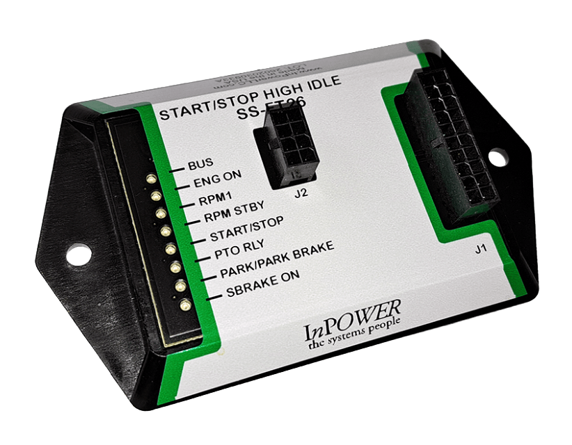


A utility truck does much of its work standing still. The U.S. Department of Energy describes the job list plainly: installing and repairing electric and telecommunication lines, powering equipment and tools, and supplying heating and cooling for workers in the cab or down a manhole (DOE Work Truck Idling Reduction). Construction fleets put their trucks through the same pattern, running equipment off the vehicle for hours at a site. Every one of those loads draws on the same 12-volt system.
How that power gets distributed decides whether the truck starts the next morning and whether a single fault stays a single fault. The practices below come from OEM body builder guidance and from the way InPower has engineered vehicle power systems since 2002.
What does power distribution mean on a utility truck?
Power distribution on a utility truck is everything between the batteries and the equipment: the feeds, fuses, grounds, and switching that carry 12-volt power to each added load.
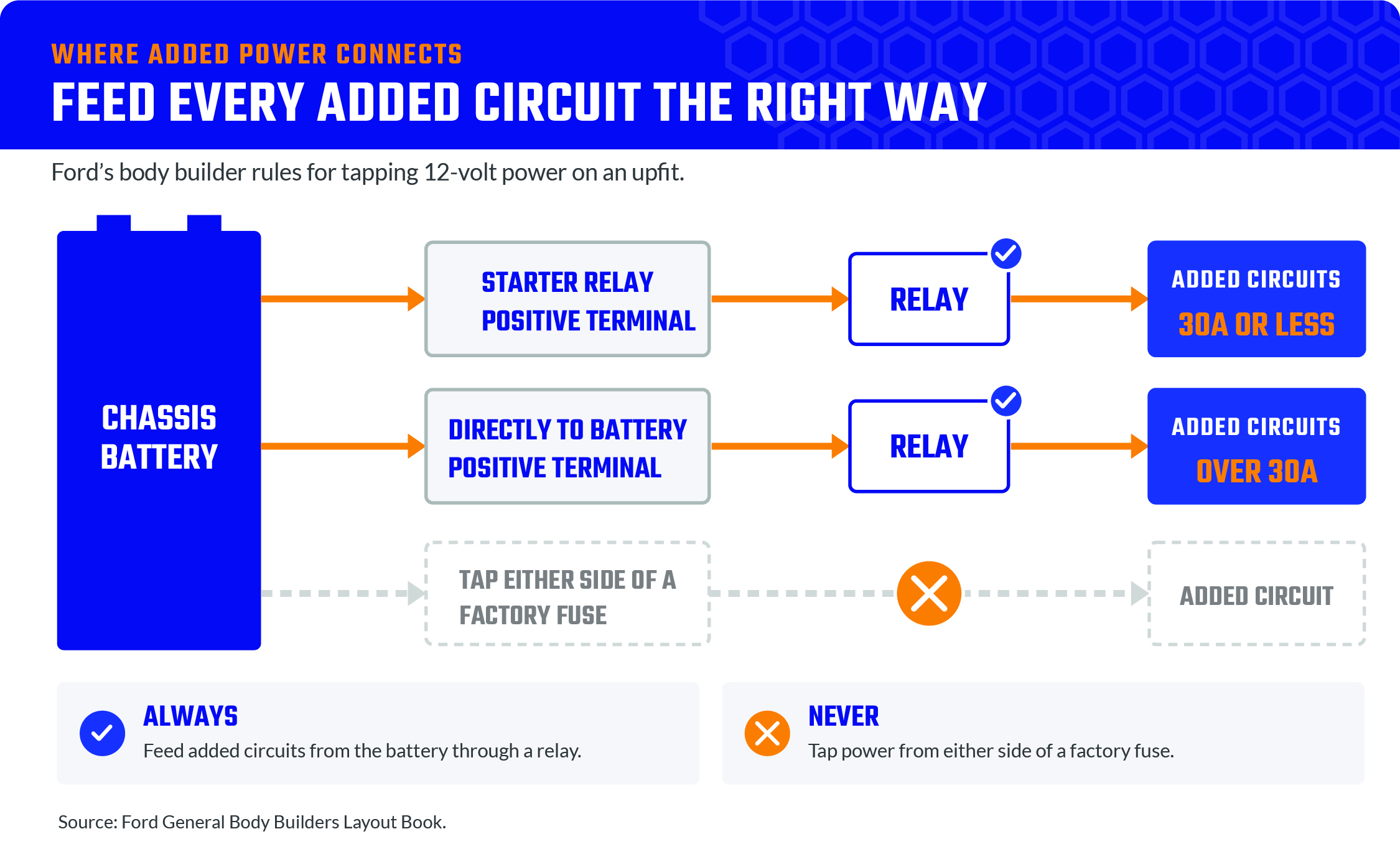
Ford’s General Body Builders Layout Book, the best-practice guide Ford publishes for upfitters across its commercial vehicle lines, sets useful ground rules for any utility truck electrical system (Ford General BBLB). Power for added circuits comes from the battery through a relay, never from a tap on either side of a factory fuse. Circuits that need 30 amps or less connect at the starter relay positive terminal, and anything larger connects directly to the battery positive terminal. We looked at how hard-wired rocker switches and relay logic arrays complicate the rest of that wiring in Multiplex Power Without Complex Code.
Why run a load analysis before adding circuits?
A load analysis confirms that each circuit can carry what you plan to add before the truck goes into service, rather than leaving a blown fuse or a damaged module to tell you.
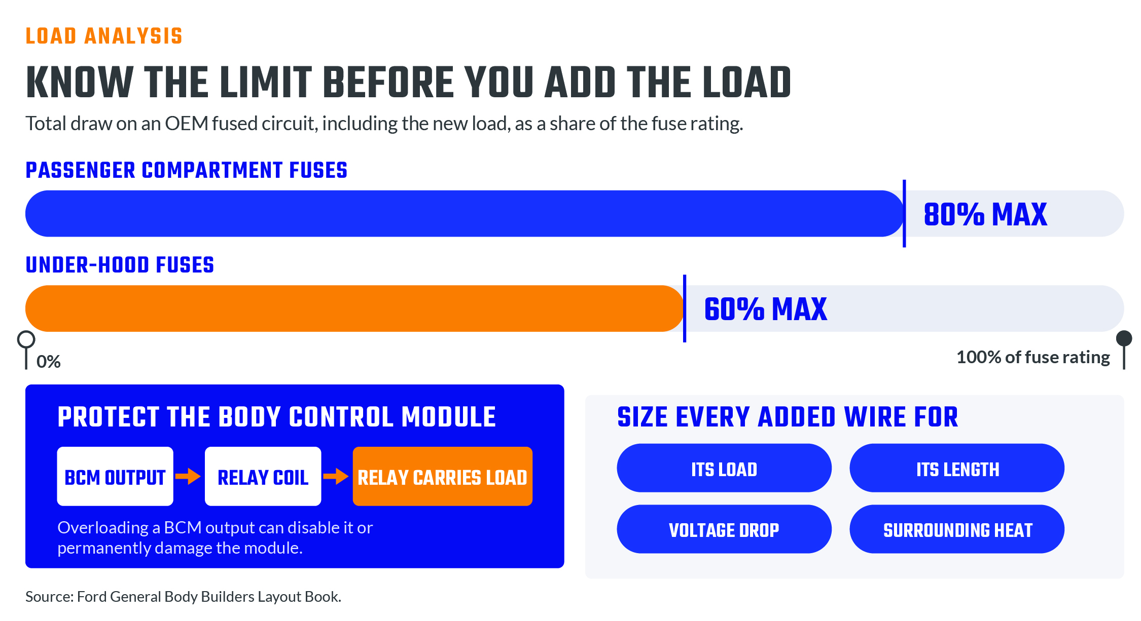
Ford requires an electrical load analysis before anyone adds loads to existing OEM fused circuits. The total draw, including the new load, must stay under 80% of the fuse rating for fuses in the passenger compartment and under 60% for fuses under the hood. Ford also warns that overloading a Body Control Module output can disable it or permanently damage the module, so it recommends using that output to drive a relay coil and letting the relay carry the load. Size every added wire for its load, its length, the voltage drop you can accept, and the heat around it.
How do you keep equipment loads from draining the starting battery?
Keep the starting battery for starting. Loads that run with the key off belong on an auxiliary battery that the alternator can charge but that stays isolated, so those loads never pull the chassis battery down.
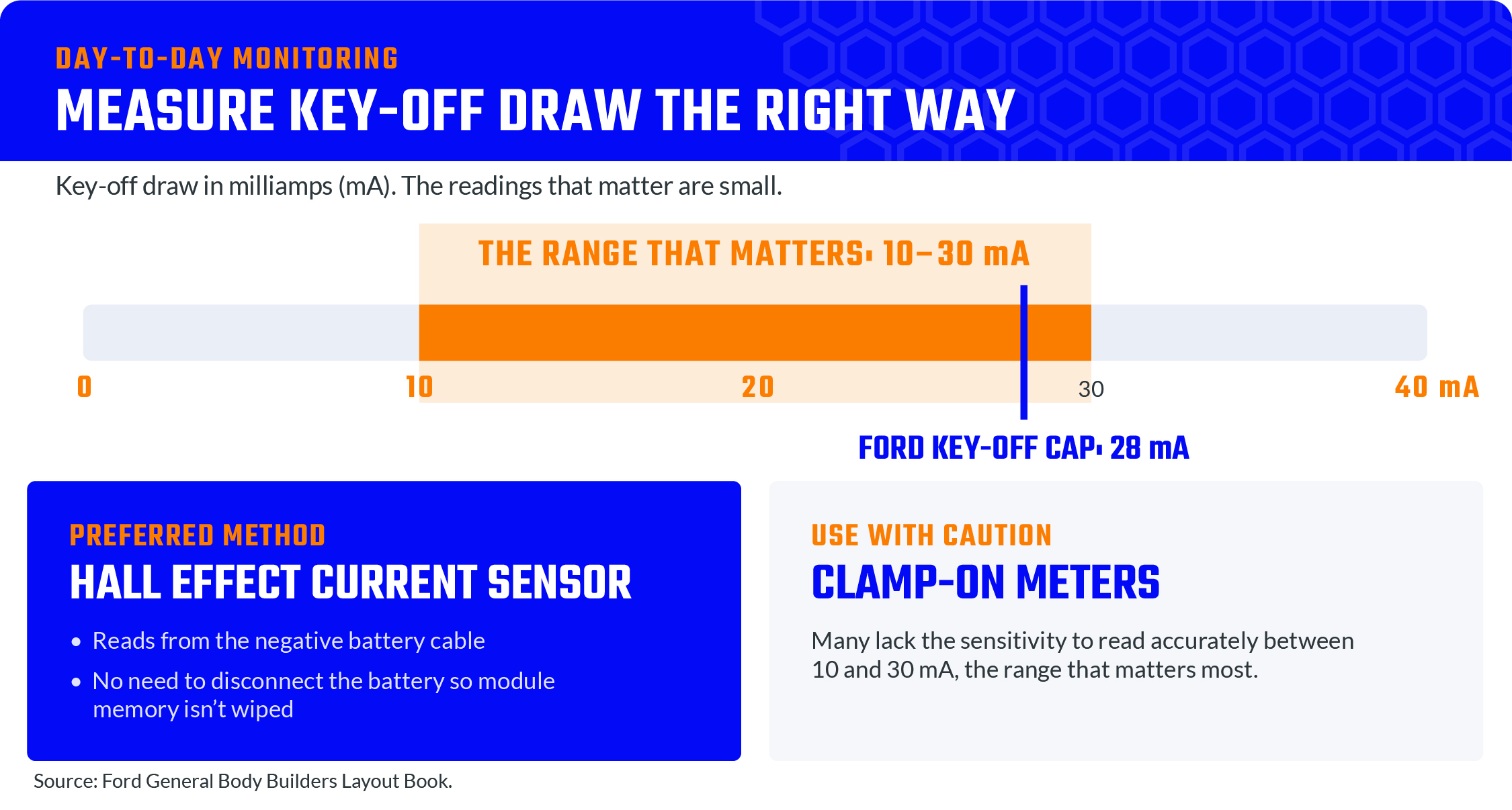
Ford caps the key-off draw of everything connected to the main batteries at 28 milliamps. Equipment that would push the draw past that should connect to an auxiliary or isolated battery. InPower’s third-generation ABS3 auxiliary battery switches handle that isolation in solid state, with no moving parts. They let the alternator charge the auxiliary battery while keeping auxiliary loads from discharging the chassis battery, and they can boost-start the vehicle from the auxiliary battery if the chassis battery runs low. High-current loads that run with the key on, 40 amps and up, take a different approach: Ford recommends multiple batteries wired in parallel, which can deliver significant power for short periods, even at low engine speed. Ford also advises keeping 12-volt batteries at 12.4 volts or higher to maintain battery life. A low voltage disconnect adds a final safeguard, shutting off loads before the battery drops too low to restart the engine. We explained how that works in What Is a Low Voltage Disconnect (and When Do You Need One)?.
How do you protect circuits so one fault stays one fault?
Give every added circuit its own fuse or circuit breaker, installed as close as possible to the point where it taps power, so a short takes out one circuit and leaves the rest of the truck working.
Label every fuse and breaker, mount them where a technician can reach them, and seal the ones under the hood against corrosion. Never raise the rating of a factory fuse. Grounds need the same discipline. Leave the OEM ground points alone, ground the body to the frame in at least two locations, and add a frame-to-engine ground cable if the path back to the battery needs help. Under the hood and under the body, Ford calls for high-temperature cross-linked wire in protective convoluted tubing, sealed connections in wet areas, and at least 12 inches of separation between high-power wiring and OEM harnesses so the power runs do not induce noise in low-power signal wires.
What does good construction fleet power management look like day to day?
Day to day, construction fleet power management comes down to measurement: knowing what each truck draws with the key off and whether its batteries hold their voltage.
Ford’s preferred method for measuring key-off draw is a Hall effect current sensor on the negative battery cable, which reads the current without disconnecting the battery and wiping module memory. Ford cautions that many clamp-on meters lack the sensitivity to read accurately between 10 and 30 milliamps, the range that matters. Monitoring built into the truck makes this easier still. That is why InPower builds DC monitoring products, low voltage disconnects, electronic relays, and switch panel systems for work trucks, from light-duty service bodies to utility bodies and high-rail trucks.
We design and manufacture everything at our own facility in Lewis Center, Ohio. If your utility or construction trucks keep fighting dead batteries or wiring nobody wants to trace, call us at 740-548-0965 and we will help you work out where the power should go.